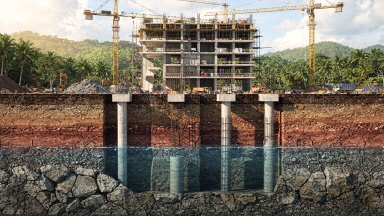
Construction drawings are the technical language of a project: they define dimensions, materials, systems and processes so that architects, engineers and builders work from the same information. A complete set includes architectural, structural, plumbing and stormwater, electrical, topographic and detail drawings. When they are missing or uncoordinated, decisions on site are left to interpretation, leading to rework, delays and cost overruns.
This article was originally published in our construction digital magazine, within the editorial line dedicated to civil engineering.
The guide is based on the experience of STI Construcciones, a Panamanian company dedicated to developing construction drawings and projects.
You can also read the version published in the November 2025 issue of Construcción en Panamá magazine (in Spanish).
What are construction drawings for?
- Defining dimensions and technical specifications precisely.
- Guiding each trade to work in sync.
- Reducing improvisation during execution.
- Planning the budget and schedule.
Types of construction drawings
| Drawing | What it contains |
|---|---|
| Architectural | Space layout, levels, access, façades and finishes. The reference for all other disciplines. |
| Structural | Foundations, columns, beams, slabs and structural materials to resist loads and earthquakes. |
| Plumbing and stormwater | Potable water, drains and stormwater, with diameters, slopes and materials. |
| Electrical and electromechanical | Circuits, outlets, fixtures, panels, protection and special systems (voice, data, security). |
| Topographic and setting-out | Elevations, contour lines and coordinates to locate the work precisely. |
| Construction details | Specific junctions and solutions: stairs, walls, joints, slabs and finishes. |
Benefits of a complete set of drawings
- Accurate execution: fewer last-minute adjustments and less waste.
- Quality and budget control: real costs are known before starting.
- Effective communication: a single reference for the whole team.
- Code compliance and safety: the project is built according to local codes.
Common drawing mistakes
- Lack of coordination between disciplines, with clashes between structure and services.
- Omission of critical construction details.
- Inconsistent dimensions between drawings.
- Wrong scales or poor legibility.
- Non-standard symbols.
- Ignoring actual site conditions.
Avoiding them requires trained professionals, technical review and digital tools. BIM coordination is now the most effective way to detect clashes between disciplines before drawings are issued, and the geotechnical study provides the real ground conditions.
Frequently asked questions
What drawings are needed to build a house?
At a minimum, architectural, structural, plumbing and electrical drawings, plus any required by the relevant municipal regulations.
What is a setting-out drawing?
One that transfers to the site, with elevations and coordinates, the exact location of the project’s elements.